We Provide Cooling Tower Solution

Views: 0 Author: Cindy Publish Time: 2026-11-04 Origin: Site


A cooling tower depends on a continuous balance of water and air to remove heat from industrial processes and HVAC systems. While components such as fans, fill media, drift eliminators, and water distribution systems receive much of the attention, one relatively small component plays an equally important role in daily operation: the cooling tower fill valve.
A cooling tower fill valve, commonly called a cooling tower makeup water valve or float valve, controls the supply of fresh water entering the tower's cold-water basin. Its job sounds simple, but its impact is significant. If the water level becomes too low, pumps may experience operating problems. If the level rises too high, water can overflow and create unnecessary waste.
So, how do you choose the right valve? What types are available, and what should you consider before purchasing one?
This guide explains cooling tower fill valve functions, operating principles, common designs, materials, selection criteria, installation, and maintenance. Whether you are replacing an existing valve or specifying equipment for a new cooling tower, understanding these details can help you make a more reliable choice.
A cooling tower fill valve is a water-control device installed on the makeup water supply line. It replenishes water lost during normal cooling tower operation and helps maintain the required water level in the cold-water basin.
Cooling towers lose water through several processes:
Evaporation: Water evaporates as it absorbs heat from the process water.
Drift: Small water droplets are carried out of the tower with the exhaust air.
Blowdown: Some circulating water is discharged to control the concentration of dissolved minerals and other contaminants.
Leaks and maintenance losses: Water may also be lost through leakage, cleaning, and other operating activities.
The makeup water system replaces these losses. The fill valve regulates how much fresh water enters the basin.
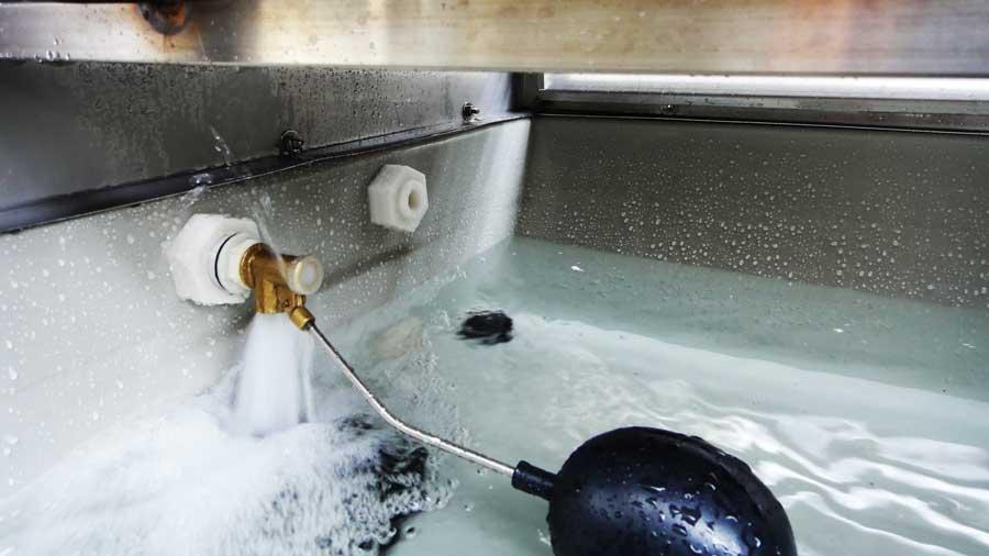
The valve responds to changes in basin water level. In a mechanical float valve, a floating ball or other buoyant component rises and falls with the water.
When the water level drops, the float moves downward and opens the valve. Fresh water enters the basin. As the basin refills, the float rises and gradually closes the valve.
This automatic process helps maintain a suitable operating level without requiring an operator to open and close the supply manually.
The term "fill" can cause confusion in cooling tower equipment searches.
Cooling tower fill media refers to PVC, PP, or other structured materials installed inside the tower to increase contact between water and air. It supports heat and mass transfer.
A cooling tower fill valve, on the other hand, controls the supply of makeup water to the basin. It does not perform the heat-transfer function of fill media.
When searching for replacement equipment, use the correct product terminology to avoid ordering the wrong component.
A properly selected fill valve helps maintain stable water levels and reduces the need for constant manual adjustment. Although it is a small part of the overall system, a malfunction can affect pumps, water consumption, and operating reliability.
The cold-water basin stores water before it returns to the cooling system. The basin must contain enough water to support the circulation pumps under the expected operating conditions.
If the water level becomes too low, the pump may experience inadequate suction conditions, air entrainment, or other problems depending on the system design. A suitable makeup valve helps keep the basin within its intended operating range.
A valve that fails to close properly may allow the basin to overflow. This wastes treated water and can cause water to collect around the cooling tower.
A valve that closes too early, becomes blocked, or cannot deliver enough water may cause the basin level to fall below the required range.
Correct sizing and adjustment help prevent both situations.
The fill valve does not directly increase cooling capacity. Instead, it supports the water supply conditions required for reliable operation.
Think of it as a gatekeeper. It does not perform the main cooling work, but it helps ensure that the system has the water it needs.
The operating principle depends on the valve design. Mechanical float valves use buoyancy, while electrically controlled systems use sensors and control devices.
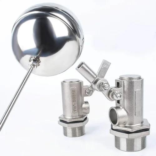
A traditional mechanical float valve contains a valve body, inlet connection, sealing element, lever or arm, and floating ball.
The float follows the basin water level. Its movement operates the valve mechanism.
When the water level falls, the float moves down and the valve opens. When the water reaches the set level, the float rises and pushes the valve toward its closed position.
The exact opening and closing behavior depends on the valve's design, linkage geometry, operating pressure, and adjustment range.
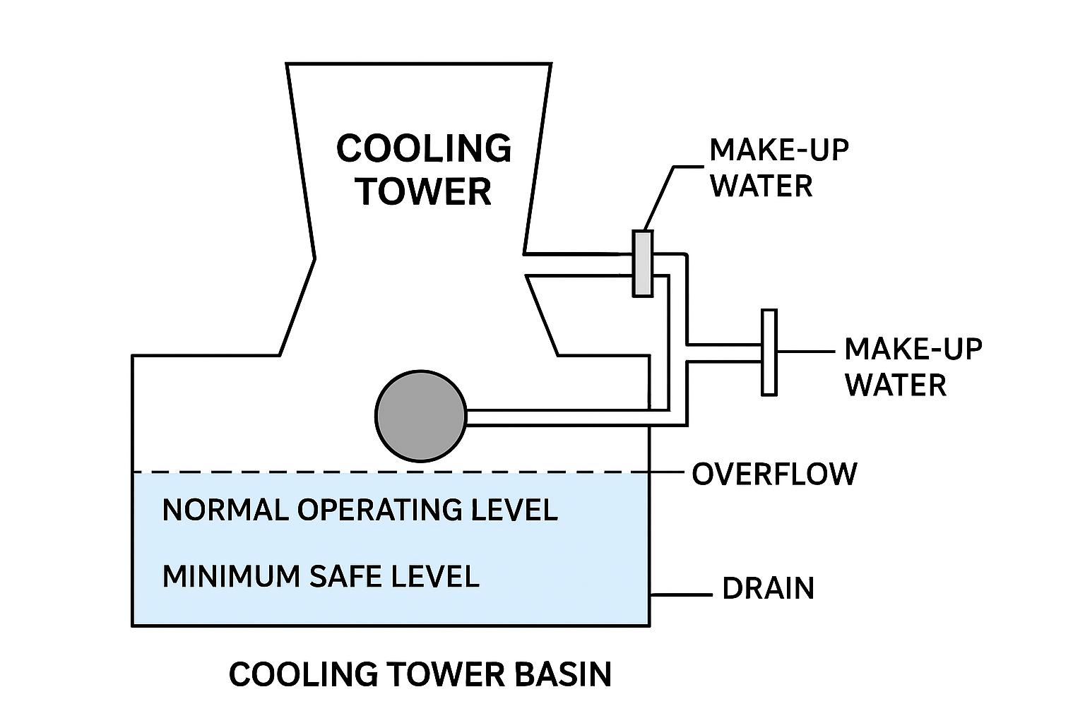
In a typical cooling tower installation, the process follows four basic steps:
Water is lost through evaporation, drift, blowdown, and other operating conditions.
The basin water level falls.
The fill valve opens and allows makeup water to enter.
Once the target level is reached, the valve closes or reduces the incoming flow.
This process repeats throughout operation.
An important point: the makeup water supply must be capable of meeting the system's actual replenishment demand. Even a correctly operating valve cannot maintain the target level if the upstream supply pressure or available flow is inadequate.
Cooling tower makeup water systems can use several types of valves. The best option depends on the tower size, water supply, control requirements, operating pressure, and maintenance preferences.
Mechanical float valves are among the most straightforward solutions for cooling tower basin level control.
They use a floating ball or buoyant element connected to a mechanical valve mechanism. No electrical power is normally required for the valve's basic operation.
Advantages include:
Simple operating principle
No electrical control power required
Relatively straightforward installation
Easy visual inspection
Suitable for many conventional basin arrangements
However, mechanical components can wear, and floats may become damaged, obstructed, or stuck. The valve must also be selected for the actual supply pressure and required flow rate.
A solenoid valve uses an electromagnetic coil to control water flow. It is generally operated by an electrical signal from a level switch, controller, or other control device.
When the control system calls for makeup water, the solenoid valve changes position and allows water to enter. When the required level is reached, the control signal changes and the valve closes.
Potential benefits include:
Integration with automatic control systems
Remote or centralized operation
Compact installation
Compatibility with level sensors and control logic
The coil voltage, valve pressure rating, flow capacity, water temperature, and electrical protection must all match the application.
A solenoid valve is not automatically a replacement for every mechanical float valve. The system needs suitable level detection and control wiring.
Motorized valves use an electric actuator to open, close, or modulate the valve. Depending on the design, they may provide on/off control or more precise adjustment.
They can be useful in larger or more automated cooling water systems where operators want the valve to respond to a central control system.
Before selecting one, check actuator power requirements, control signals, operating time, valve characteristics, and the intended failure position.
An electronic water-level control arrangement uses sensors or level switches to detect the basin level and send signals to a control device.
The controller then operates a solenoid or motorized valve.
This arrangement can provide more flexible control than a basic mechanical float valve. It may also support alarms or integration with a building management system or industrial control platform.
However, the complete system includes more than the valve itself. Sensor reliability, wiring, controller configuration, power supply, and maintenance access all matter.
The exact construction varies by manufacturer and valve type, but a typical mechanical float valve may include:
Valve body: Contains the internal flow passage and supports the valve assembly.
Inlet connection: Connects the valve to the makeup water pipeline.
Sealing element: Controls water flow when the valve closes.
Lever or operating arm: Transfers movement from the float to the valve mechanism.
Float ball: Provides buoyancy and follows the basin water level.
Adjustment mechanism: Allows the closing level to be changed on designs that support adjustment.
Mounting hardware: Secures the valve in its intended installation position.
For electrically operated systems, the main components may also include a solenoid coil, actuator, level sensor, controller, and electrical connections.
When replacing a valve, do not identify it by appearance alone. Check the connection dimensions, pressure rating, flow capacity, mounting arrangement, and control requirements.
Cooling tower water conditions can vary considerably. The makeup water may contain dissolved minerals, suspended solids, treatment chemicals, and other substances that influence material selection.
Brass and bronze are commonly used in some mechanical valve bodies and fittings.
They offer useful mechanical properties and are available in many connection configurations. However, their suitability depends on water chemistry, temperature, and the specific alloy.
Do not assume that every brass or bronze valve is suitable for every cooling tower. Check the manufacturer's compatibility guidance.
Stainless steel is often considered where corrosion resistance and mechanical strength are important.
Different stainless steel grades offer different levels of corrosion resistance. Chloride concentration, temperature, deposits, and cleaning chemicals can influence performance.
Selecting stainless steel without checking the actual water conditions may lead to an unsuitable choice.
Some valve bodies, floats, and internal components are manufactured from engineering plastics.
Depending on the material, plastic components can offer low weight and resistance to certain forms of corrosion. Their limitations may include temperature restrictions, pressure limits, UV exposure, and mechanical strength.
For outdoor cooling tower installations, confirm that exposed components are suitable for the expected environment.
Choosing a cooling tower fill valve is not simply a matter of matching the pipe connection. The valve must supply enough water, operate reliably under the available pressure, and fit the basin arrangement.
Start by estimating the makeup water demand.
The required flow depends on cooling tower heat load, evaporation, drift, blowdown, operating conditions, and any additional water losses.
The valve should be able to deliver the required replenishment flow under the actual operating pressure. A valve that is too small may refill the basin slowly, while an oversized valve may cause control difficulties or water hammer in some installations.
Use the manufacturer's flow data and the system's design conditions rather than relying on nominal pipe size alone.
Water supply pressure affects valve performance.
A valve may have a minimum and maximum operating pressure. Some designs require a minimum differential pressure to function correctly, while others are intended for different pressure conditions.
Before ordering, confirm:
Normal supply pressure
Minimum and maximum pressure
Pressure fluctuations
Required valve pressure rating
Whether a pressure regulator is needed
The valve must be compatible with the real operating conditions, not just the nominal pressure shown on a general system drawing.
Check the inlet connection size and type. Common connection arrangements may include threaded, flanged, or other manufacturer-specific designs.
Also verify the available installation space, orientation, and distance between the valve and basin wall.
A valve with the correct nominal diameter may still be unsuitable if its thread standard, flange dimensions, or mounting arrangement does not match the existing pipeline.
Water quality is a major factor in valve service life.
Hard water can contribute to mineral deposits. Suspended particles may interfere with sealing surfaces or small flow passages. Certain chemical conditions may accelerate corrosion.
Consider the following before selecting materials:
Water hardness
Chloride concentration
pH
Suspended solids
Water treatment chemicals
Operating temperature
Where water contains debris, an appropriately selected upstream strainer may help protect the valve. The strainer must be accessible and maintained so that it does not become a restriction itself.
A mechanical float valve may be suitable for a simple basin arrangement. A solenoid or motorized valve may be more appropriate where automatic control and remote monitoring are required.
Ask these questions:
Is local mechanical control sufficient?
Is an electrical level sensor already installed?
Does the system require remote monitoring?
What power supply is available?
Should the valve operate in an on/off or modulating mode?
What should happen if power or a control signal is lost?
The valve and control system should be designed as one coordinated arrangement.
Correct installation helps prevent leakage, poor level control, and unnecessary maintenance. Always follow the valve manufacturer's instructions and the site's safety procedures.
Before installation, isolate the makeup water supply and depressurize the relevant pipeline.
Check the pipe connection, valve mounting location, and available clearance. Remove dirt, scale, and debris from the connection area.
If the system design calls for an isolation valve, strainer, or pressure regulator, confirm that each component is installed in the correct position and orientation.
For a mechanical float valve, secure the valve body and confirm that the float can move freely.
The float should not hit the basin wall, pipework, structural members, or other equipment during normal operation.
Adjust the float according to the manufacturer's instructions so that the valve closes at the required basin level. Avoid bending or modifying components unless the valve design specifically permits the adjustment.
After installation, slowly restore the water supply and inspect all connections for leakage.
Observe the valve as the basin fills. Confirm that it opens when the level drops and closes at the intended level.
Check that:
The float moves freely.
The valve closes without continuous dripping.
The basin does not overflow.
The makeup water flow is sufficient.
The valve and pipework remain stable.
Electrical controls, where fitted, respond correctly.
Record the final water level and any adjustment made. This information can help future maintenance teams.
Even a well-selected valve can develop problems over time. Early inspection can prevent a small fault from becoming a larger water management issue.
A valve may continue passing water after it should have closed.
Possible causes include worn seals, debris trapped in the sealing area, damaged valve seats, excessive pressure, or incorrect adjustment.
First, isolate the supply safely and inspect the valve according to the manufacturer's service instructions. Cleaning may resolve some contamination-related problems, but damaged sealing components may need replacement.
A float that cannot move freely may fail to operate the valve correctly.
Check for deposits, physical damage, interference from nearby components, or water entering a damaged float.
The float must be able to rise and fall with the basin level. Replace damaged components with compatible parts rather than improvising a repair.
If the basin level keeps falling even though the valve appears to open, the problem may not be the valve alone.
Possible causes include:
Low upstream water pressure
An undersized supply pipe
A blocked strainer
A partially closed isolation valve
A valve with insufficient flow capacity
Makeup demand exceeding available supply
Check the complete water supply path before replacing the valve.
Overflow may occur when the valve does not close, the float is incorrectly adjusted, or the level-control system fails.
Inspect the mechanical linkage, sealing parts, float movement, and control signals as applicable.
Where overflow could cause damage, consider whether an independent high-level alarm or overflow protection arrangement is appropriate for the installation.
Regular inspection helps keep the makeup water system reliable. A practical maintenance routine should include:
Inspect the valve body: Look for corrosion, cracks, deformation, and external leakage.
Check float movement: Confirm that the float moves smoothly without obstruction.
Inspect sealing components: Look for wear, deposits, and signs of continuous leakage.
Clean strainers: Remove accumulated debris according to the maintenance schedule.
Verify the closing level: Confirm that the valve maintains the intended basin water level.
Check electrical components: For automated systems, inspect wiring, sensors, coils, actuators, and controller signals.
Record recurring problems: Track leakage, slow filling, frequent adjustments, and component replacements.
Inspection frequency should reflect operating hours, water quality, equipment design, and the manufacturer's recommendations. Systems operating with dirty or mineral-rich water may require more frequent checks.
Cleaning or adjustment may solve minor problems, but replacement is often the better option when the valve can no longer operate reliably.
Consider replacement when:
The valve continues leaking after appropriate cleaning and service.
The valve body is cracked, severely corroded, or damaged.
The float is damaged or cannot maintain buoyancy.
Internal parts are excessively worn.
The valve cannot provide the required makeup flow.
Replacement parts are unavailable.
The existing valve is incompatible with updated system requirements.
Before purchasing a replacement, record the old valve's model, connection size, material, pressure rating, flow capacity, and mounting dimensions. If these details are unavailable, take clear photographs and measurements.
This reduces the risk of ordering a valve that looks similar but does not fit or perform correctly.
Several devices may appear in a cooling tower makeup water system, but they do not all perform the same job.
| Device | Main Function | Typical Application |
|---|---|---|
| Mechanical float valve | Controls water through float movement | Automatic basin replenishment |
| Solenoid valve | Opens or closes through an electrical signal | Automated makeup water control |
| Motorized control valve | Provides actuated on/off or modulating control | Integrated water management systems |
| Level switch | Detects a preset water level | Pump or valve control signals |
| Level transmitter | Measures water level continuously or at intervals | Monitoring and automated control |
| Isolation valve | Stops water flow for maintenance | Pipeline isolation |
A level switch or transmitter does not necessarily control water flow by itself. It normally sends information to a controller or another device.
Likewise, an isolation valve is not a substitute for an automatic makeup water valve. Each component has a different role in the system.
A reliable supplier should help you confirm that the valve matches your operating conditions, not simply offer a product based on pipe size.
Before placing an order, consider the following points.
Ask for technical information covering:
Valve type and operating principle
Nominal connection size
Flow capacity
Working pressure range
Body and float materials
Temperature limitations
Connection standard
Installation requirements
Check whether the supplier can provide product drawings, material information, inspection records, and relevant test documentation.
For replacement projects, compatibility is especially important. A technically sound valve may still be unsuitable if its dimensions or operating characteristics do not match the existing system.
A supplier should be able to clarify technical questions before shipment and provide guidance when installation or replacement issues arise.
For international buyers, also consider packaging, export documentation, delivery arrangements, and communication during the procurement process.
A fill valve is only one part of a complete water management strategy. To maintain reliable operation, combine appropriate valve selection with regular system checks.
Set the correct operating level. Follow the cooling tower manufacturer's requirements and consider pump suction conditions, basin geometry, and the system's operating range.
Avoid unnecessary overfilling. Excessively high water levels can cause overflow and waste treated makeup water.
Monitor makeup water consumption. A sudden increase may indicate leakage, excessive blowdown, drift problems, or a valve that is not closing properly.
Maintain water treatment. Scale, corrosion, and biological growth can affect the cooling tower and its water-control components.
Use independent protection where appropriate. For critical installations, a high-level alarm or other protective arrangement can provide an additional warning if the primary valve fails.
Good water level control is not just about keeping the basin full. It is about supplying the right amount of water under changing operating conditions.
Selecting cooling tower components requires more than comparing product prices. Buyers need to understand equipment compatibility, operating conditions, material requirements, and long-term maintenance needs.
Mach Industry (Zhejiang) Co.,Ltd. focuses on cooling tower products and related industrial cooling solutions. When evaluating a cooling tower project or replacement requirement, buyers can visit the company's website to learn more about its products and discuss their application needs.
Website: https://www.machcooling.com
For a cooling tower fill valve inquiry, it is useful to prepare the following information before contacting a supplier:
Cooling tower model or equipment details
Existing valve photographs
Inlet connection size and type
Available water supply pressure
Required makeup water flow rate
Preferred valve material
Mechanical or electrical control requirements
Installation dimensions and operating conditions
Providing these details makes it easier to identify a suitable product and avoid unnecessary compatibility problems.
For industrial cooling tower projects, Mach Industry aims to support customers in identifying appropriate cooling equipment and component solutions based on their technical requirements.
A cooling tower fill valve controls the makeup water entering the cooling tower basin. It helps replace water lost through evaporation, drift, blowdown, and other operating losses, maintaining the basin within its required water level range.
Not necessarily. Many cooling towers use mechanical float valves, but others use solenoid valves, motorized valves, or electronic level-control systems. The correct arrangement depends on the cooling tower design and automation requirements.
The correct size depends on the required makeup water flow, available supply pressure, pipe connection, and valve flow characteristics. Do not select a valve based only on the existing pipe diameter. Confirm the system requirements and manufacturer's specifications.
There is no universal replacement interval. Service life depends on material quality, water chemistry, operating pressure, maintenance, and usage. Inspect the valve regularly and replace it when leakage, damage, or unreliable operation cannot be corrected through appropriate servicing.
A properly functioning valve can help prevent unnecessary overflow and water waste. However, it does not reduce the water naturally required for evaporation or the water discharged through necessary blowdown. Overall water efficiency also depends on drift control, water treatment, and operating practices.
A cooling tower fill valve may be a small component, but it plays an essential role in maintaining the correct basin water level. By controlling makeup water, it helps protect the water supply conditions needed for reliable cooling tower operation.
Mechanical float valves offer a simple solution for many installations, while solenoid, motorized, and electronic control arrangements can support more automated systems. The right choice depends on flow capacity, pressure, connection size, material compatibility, water quality, and control requirements.
Before purchasing a replacement, take time to check the existing installation and confirm the actual operating conditions. A valve that fits the pipe but cannot meet the system's requirements is not the right valve.
For more information about cooling tower products and industrial cooling solutions, visit Mach Industry (Zhejiang) Co.,Ltd. at https://www.machcooling.com.