We Provide Cooling Tower Solution
Views: 0 Author: Site Editor Publish Time: 2025-12-10 Origin: Site


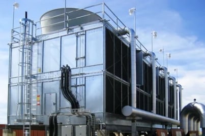
Selecting the right cooling tower size is a critical step when you design a “water cooling tower system,” whether for HVAC, industrial processes, or chilled-water applications. A correctly sized tower will meet your system’s “water cooled tower” requirements, deliver the necessary cooling capacity, support proper “cooling tower water treatment” (or “closed loop cooling tower water treatment” for closed-circuit/closed-loop systems), and ensure stable long-term performance with efficient water flow and heat rejection. In this article, we’ll walk through how to size a cooling tower, what data you need, the formulas involved, and how a manufacturer like MachCooling (https://www.machcooling.com/) can help.


Before you perform any sizing calculation, you need to collect baseline data about your system. Key parameters include:
Water flow rate (Q) — often in gallons per minute (GPM) or cubic metres per hour (m³/h). (Aggreko)
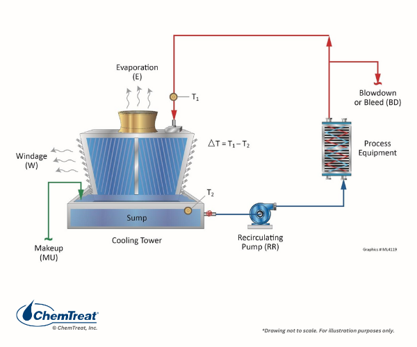
Hot water inlet temperature (T₁) — the temperature of water entering the tower (after condenser, process, or heat exchanger). (Mach Cooling)
Desired cold water outlet temperature (T₂) — target after cooling. (HMCoolingTower)
Temperature difference (ΔT = T₁ – T₂) — often referred to as the “range” of cooling. (ICSThailand)
Ambient air conditions, especially wet-bulb temperature (WBT) — because evaporative cooling depends on humidity and ambient air state. (ASHRAE 手册在线)
System heat load — either derived from process or chiller requirements (in BTU/hr or kW), or inferred from flow + temperature drop. (Mach Cooling)
With these inputs, you can size a cooling tower to meet your heat rejection needs.
A widely used formula to estimate the heat load a cooling tower must handle is:
Heat Load (BTU/hr) = Q × 500 × (T₁ – T₂)
Q = water flow rate in GPM
ΔT = T₁ – T₂ in °F
“500” is a constant combining water density and specific heat (approx. 8.33 lb/gal × 60 min × 1 BTU/lb-°F) (Pacminerals)
If you need the cooling tower capacity in “tons of cooling”, use:
Cooling Capacity (tons) = (Q × 500 × ΔT) / 12,000
Since one “refrigeration ton” = 12,000 BTU/hr by convention. (Mach Cooling)
Example: Suppose Q = 500 GPM, hot-water inlet T₁ = 100 °F, desired outlet T₂ = 85 °F → ΔT = 15 °F
Heat Load = 500 × 500 × 15 = 3,750,000 BTU/hr
Cooling Capacity = 3,750,000 / 12,000 ≈ 312.5 tons
So you’d need a cooling tower with ~312.5-ton capacity (or slightly higher for margin). (Mach Cooling)
Sometimes you know the heat load and desired ΔT but need to find the required flow rate Q. Rearranging the formula gives:
Q (GPM) = Heat Load (BTU/hr) / [500 × ΔT]
This helps size the circulation pumps and specify water flow for the cooling tower system. (Sivo Blog)
While the basic calculation gives a starting point, real-world cooling tower performance depends on more than just flow and ΔT.
The ambient wet-bulb temperature (WBT) is a critical limiting factor — the cooler water can get (after evaporative cooling) is roughly equal to WBT plus a small “approach” (Δ between cold-water exit and WBT). (ASHRAE 手册在线)
Typical towers might achieve an approach of 5–10 °F above WBT, depending on design and conditions. (HMCoolingTower)
If your desired cold-water temperature (T₂) is too close to ambient WBT, you may need a larger tower, more airflow, or better fill media to achieve it.
Therefore, sizing should always cross-check that T₂ is realistically achievable given local WBT and tower design.
As noted by MachCooling’s guidelines, after calculating a theoretical capacity you should adjust for real-world conditions (water quality, ambient humidity, system losses, safety margin) via a Design Correction Factor (DCF). (Mach Cooling)
Also, consider:
Water treatment needs (especially for open “blowdown water cooling tower” systems) — scale, fouling, corrosion can reduce heat transfer efficiency and require larger capacity. (Mach Cooling)
Type of system: if you have a “chilled water cooling tower” or “closed loop cooling tower water treatment” for sensitive process water, additional capacity might be needed to account for fluid properties, fouling risk, or required redundancy.
System piping, pump capability, and water distribution system — ensure flow rates calculated can be reliably delivered.
Here’s a practical step-by-step workflow to size a cooling tower effectively:
Determine system heat load (from process, chiller condenser, or expected dissipation) in BTU/hr (or kW) — or gather chiller tonnage rating.
Decide target hot-water inlet (T₁) and cold-water outlet (T₂) temperatures → compute ΔT.
Estimate circulating water flow rate Q (or compute Q using heat load & ΔT if unknown).
Compute theoretical cooling capacity (tons) using formula above.
Check ambient conditions — particularly worst-case wet-bulb temperature; ensure desired T₂ is realistically achievable (check approach margin).
Factor in a safety/over-capacity margin (e.g. 10–20%) and apply a Design Correction Factor (DCF) to account for losses (water quality, scaling, fouling, system inefficiencies, seasonal variations).
Review and select a cooling tower model whose certified capacity meets or exceeds the corrected requirement — in terms of GPM, tons, ΔT, and airflow.
Confirm the rest of your system (pumps, piping, water treatment system, distribution system) supports the required flow and water quality.
For “water cooled tower,” “blowdown water cooling tower,” or “chilled water cooling tower” applications, coordinate with water-treatment and blowdown strategy to maintain performance over time.
Here’s a sample sizing table to guide you:
| Parameter | Value / Input | Note / Source |
|---|---|---|
| Heat load | e.g. 3,750,000 BTU/hr | From process / condenser / chiller |
| Water flow rate (Q) | 500 GPM | Known or calculated |
| Hot water inlet temp (T₁) | 100 °F | From system specification |
| Desired cold water outlet temp (T₂) | 85 °F | Target requirement |
| ΔT (range) | 15 °F | T₁ – T₂ |
| Theoretical capacity | ~312.5 tons | (500 × Q × ΔT)/12,000 |
| Ambient wet-bulb temp (WBT) | e.g. 78 °F | Local design condition |
| Safety / correction factor (DCF) | e.g. 1.1 (10% margin) | Depends on water quality etc. |
| Final selection capacity | ~340–350 tons | Tower should be rated ≥ corrected capacity |
Working with a manufacturer like MachCooling adds value:
MachCooling publishes detailed sizing guides and formulas — including the same heat-load and capacity calculations described above — allowing you to compute required tonnage and water flow, and then match to their tower models. (Mach Cooling)
Their catalogue includes “water cooling tower,” “water cooled tower,” open-circuit towers and variants suited for “blowdown water cooling tower” applications, as well as closed-loop or “chilled water cooling tower” solutions — giving flexibility depending on application and water treatment constraints.
They can help specify towers to match required flow rate, ΔT, water quality, environmental conditions, and provide proper documentation for performance curves, which is important when ambient conditions vary or when you need a safety margin for future load increases.
MachCooling’s support ensures that downstream components (pumps, piping, water treatment or filtration, blowdown water cooling tower design) are considered when selecting tower size — not just the tower itself.
By combining your load calculations with MachCooling’s product data and engineering support, you reduce the risk of undersized towers (leading to insufficient cooling) or oversized towers (wasted cost, excessive footprint, inefficiency).
Sizing a cooling tower starts with knowing your system’s heat load, circulating water flow, and the temperature drop (ΔT) required.
Use the standard formula Heat Load = Q × 500 × ΔT (or its tonnage conversion) to get a preliminary sizing.
Don’t forget real-world factors: ambient wet-bulb temperature, heat transfer losses, water quality, maintenance, and system inefficiencies — apply a design correction margin.
Always cross-check that your desired outlet water temperature is feasible given local climate and tower design (through “approach” calculation).
Choose a cooling tower (open-circuit or closed-loop) from a reputable manufacturer like MachCooling — whose documented performance, product range, and engineering support help ensure correct sizing, compatibility, and long-term reliability.


