Views: 0 Author: Site Editor Publish Time: 2026-01-14 Origin: Site


Industrial cooling systems can look overwhelming at first glance. Pipes twist and turn, pumps hum nonstop, and massive equipment quietly moves heat away from critical processes. That’s exactly why an industrial chiller cooling tower diagram is so important. It turns complexity into clarity, helping engineers, operators, and decision-makers understand how heat flows, how water circulates, and how the entire system works together as one.
In this article, we’ll walk through an industrial chiller cooling tower diagram step by step—breaking down components, explaining water and heat flow, and showing why good system design makes all the difference in efficiency and reliability.
At the heart of many industrial facilities lies a water-cooled chiller system paired with a cooling tower. The chiller removes heat from process water or building systems, while the cooling tower rejects that heat to the atmosphere. Think of it like teamwork: the chiller captures the heat, and the cooling tower releases it.
Without this partnership, factories would overheat, production would slow, and energy costs would rise sharply. That’s why understanding the diagram behind the system is so valuable—it shows how every part supports the whole.

An industrial chiller cooling tower diagram is a visual representation of the cooling system layout. It illustrates how chillers, cooling towers, pumps, piping, and valves connect and interact.
More than just a drawing, it’s a roadmap. Engineers use it for system design, operators rely on it for daily operation, and maintenance teams turn to it when troubleshooting issues.
A well-made diagram helps prevent costly mistakes. It clarifies flow direction, equipment placement, and control logic before installation even begins. In many cases, a clear diagram can save more money than any single efficiency upgrade.
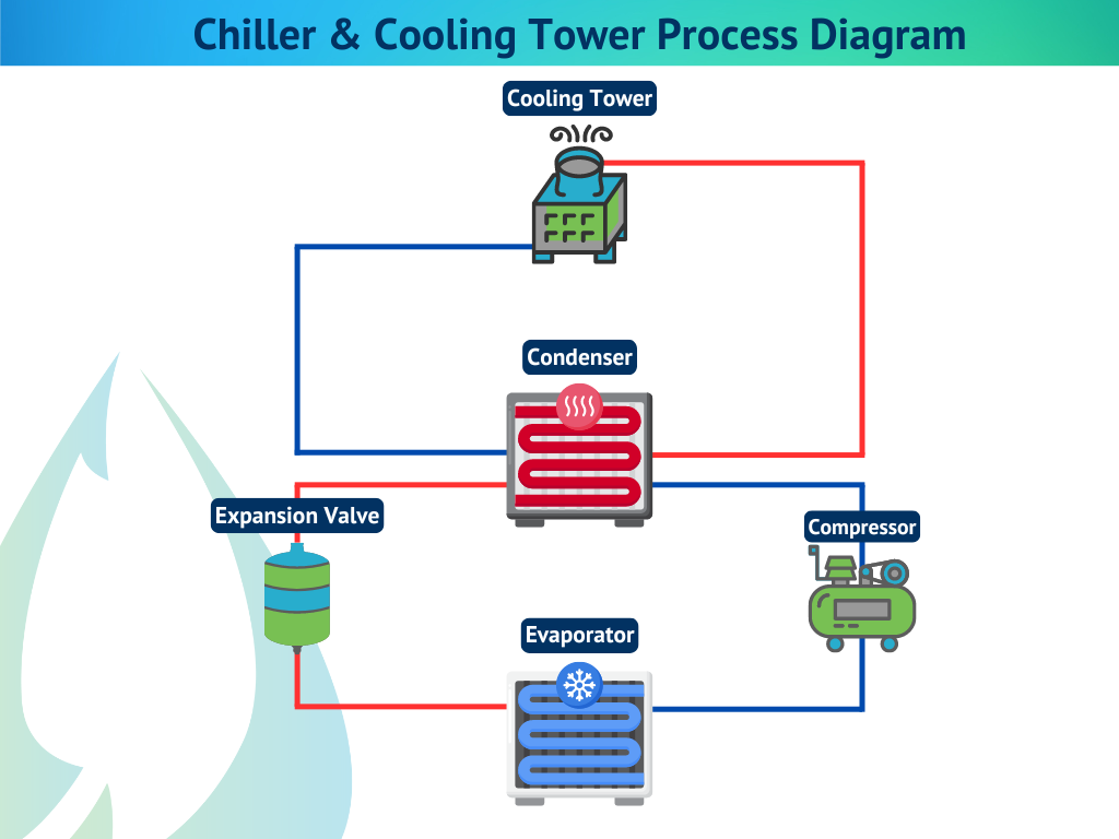
To understand the diagram, you first need to understand how chillers and cooling towers work together.
Inside the chiller, warm process or building water passes through the evaporator. Heat transfers from the water to the refrigerant, cooling the water before it returns to the system. The refrigerant then carries that heat onward.
That captured heat moves to the condenser, where condenser water absorbs it and flows to the cooling tower. Inside the cooling tower, evaporation removes the heat, releasing it into the atmosphere.

A typical diagram highlights several key components, each playing a critical role.
The chiller is the system’s control center. It determines cooling capacity, temperature stability, and overall efficiency.
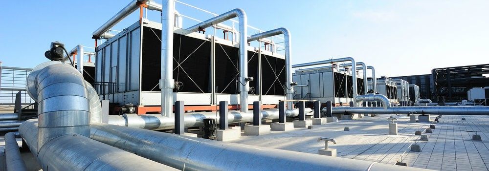
The cooling tower acts as the system’s exhaust. Its performance directly affects chiller efficiency and energy consumption.
These pumps circulate water between the chiller and the cooling tower, maintaining continuous heat transfer.
Piping connects all components, while valves regulate flow, isolate equipment, and support maintenance operations.
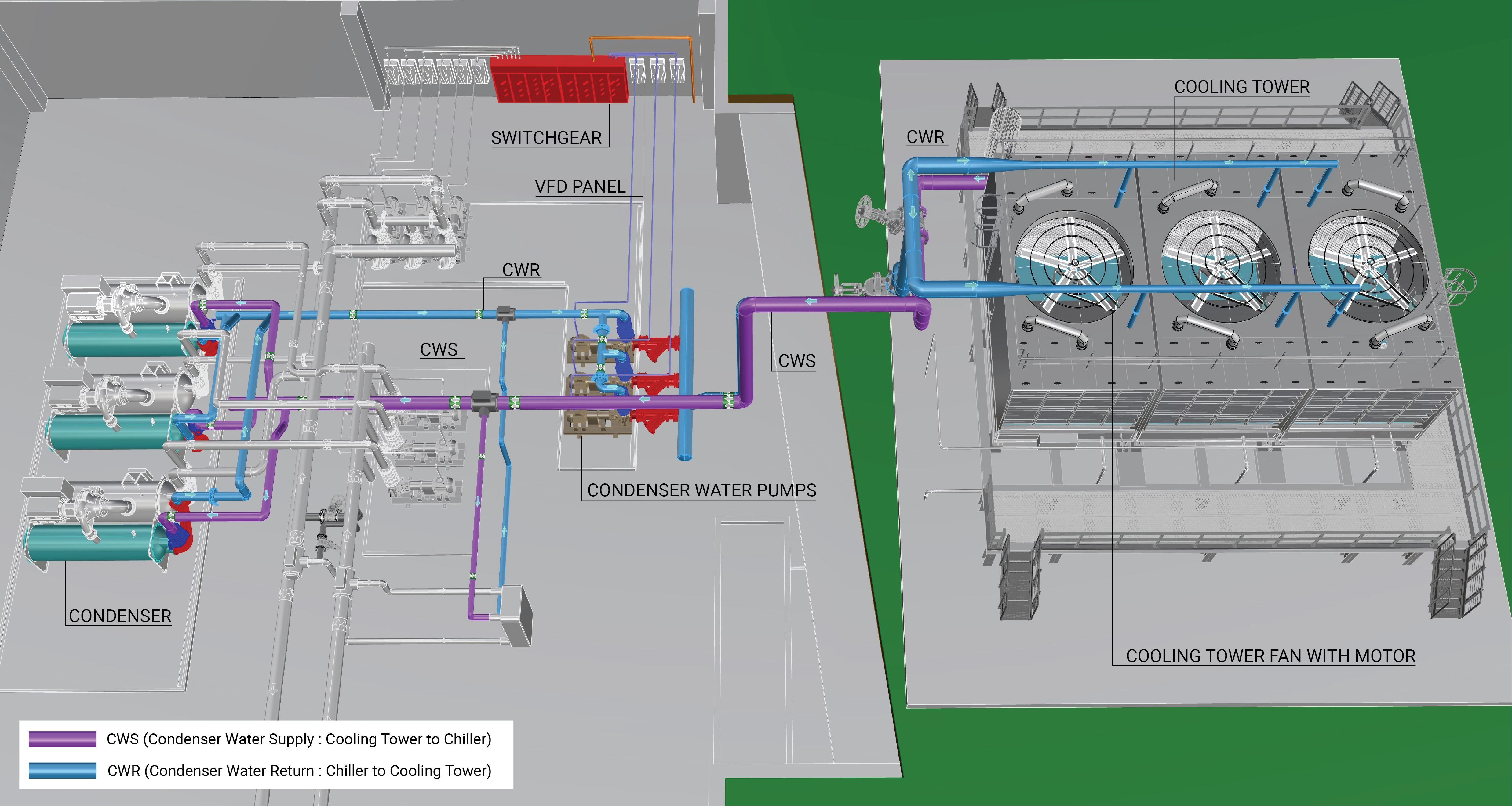
One of the most important sections of the diagram is the condenser water loop.
Warm condenser water leaves the chiller and travels to the cooling tower. After releasing heat, cooler water returns to the chiller. This closed loop runs continuously during operation.
Understanding this loop helps diagnose common problems like high condenser pressure or reduced cooling capacity.
Industrial chiller cooling tower diagrams visually show how heat flows through the system. Arrows indicate water direction, temperature changes, and energy movement.
This visualization makes it easier to identify inefficiencies, such as insufficient cooling tower capacity or improper flow balance.
Not all systems look the same. Diagrams vary depending on system type.
In open systems, water is exposed directly to air. These systems are efficient and widely used in heavy industry but require effective water treatment.
Closed systems isolate process fluid from air using a heat exchanger. They reduce contamination and maintenance but add complexity.
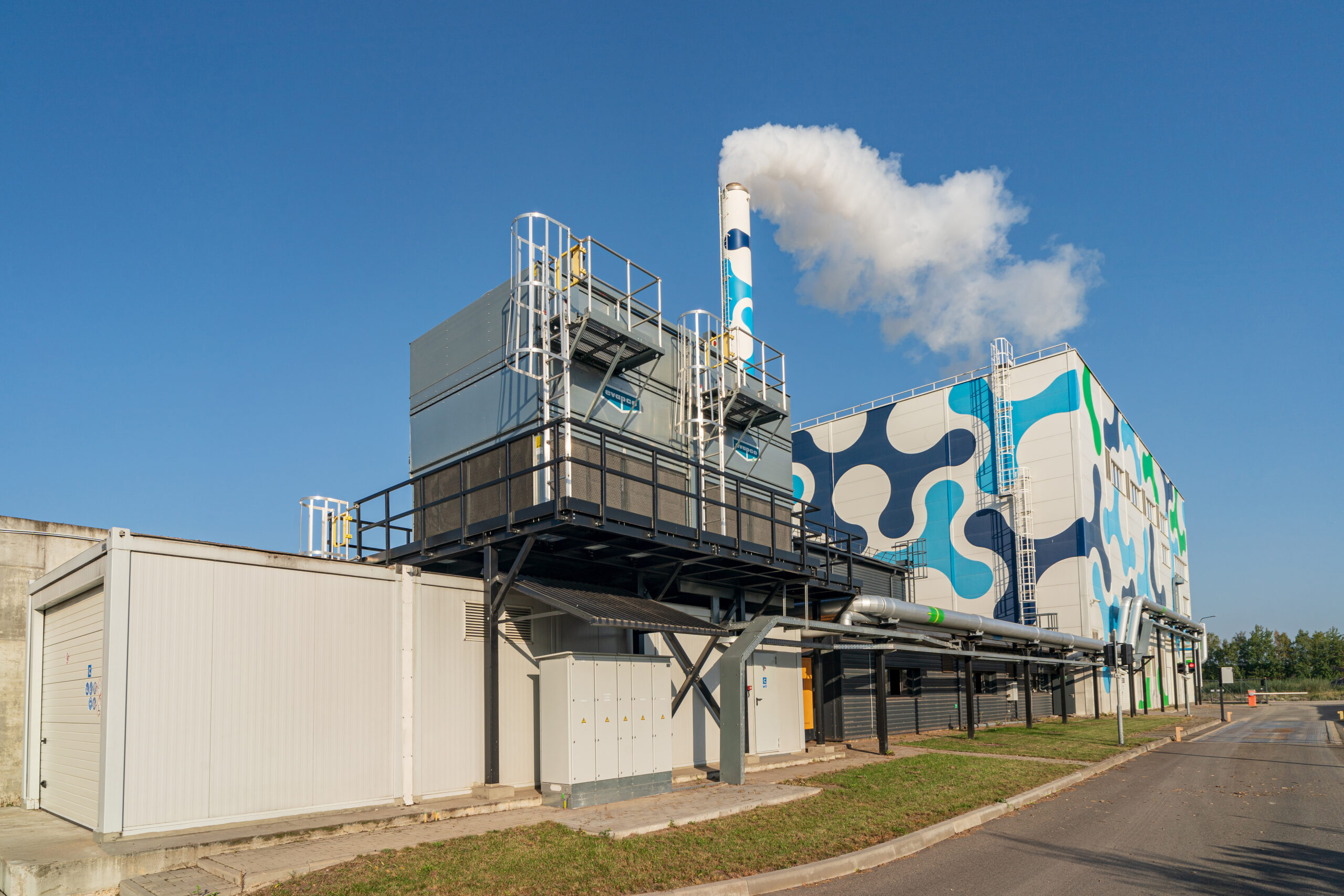
These diagrams are essential across multiple industries.
From chemical processing to plastics and steel production, diagrams help engineers design systems that handle high and variable heat loads.
In power plants, accurate cooling diagrams are critical for safety, efficiency, and regulatory compliance.
Diagrams often expose design issues early, such as:
Oversized or undersized cooling towers
Poor pump placement
Incorrect flow direction
Insufficient maintenance access
Catching these problems on paper is far cheaper than fixing them in the field.
Start with the chiller. Follow the condenser water line to the cooling tower, then trace it back. Once you understand the loop, the rest of the diagram becomes intuitive.
Well-designed diagrams reveal opportunities for optimization, including:
Variable-speed pumps and fans
Improved flow balance
Reduced energy consumption
Even small adjustments can deliver significant savings in large industrial systems.
Operators rely on diagrams to locate isolation valves, drain points, and service access areas. Clear diagrams reduce downtime and make maintenance safer and faster.
Chillers and cooling towers should never be selected independently. Diagrams ensure both components are properly matched for capacity, flow rate, and operating conditions.
Experienced cooling tower manufacturers don’t just supply equipment—they support system-level design. Clear diagrams help ensure cooling towers perform as intended under real operating conditions.
With extensive experience in industrial cooling tower manufacturing, Mach Cooling provides cooling towers designed to integrate seamlessly with chiller systems. Their engineering-focused approach helps simplify diagrams, improve performance, and reduce long-term operating costs.
An industrial chiller cooling tower diagram is far more than a technical drawing. It’s a blueprint for efficiency, reliability, and long-term performance. When you understand the diagram, you understand the system—and that understanding leads to smarter design, smoother operation, and lower costs.
In industrial cooling, clarity always pays off.


